Bracing systems
The overturning forces from truss side loads in hall structures must be dissipated via bracing braces or sheaves. The tilting forces of the beams in this area must be transferred to the bracing panels via appropriate compression or tension members or via trapezoidal steel sheets. The distance between the holding points or the fixing points on the beam is usually 5 – 7 m and is determined by the structural engineer.
The bracing is often also designed to transfer wind forces to the gable ends. The gable supports are then stored in a suspended position and can be easily dismantled or relocated in the event of a later hall extension. The bracing can be executed using steel crosses or compression- and tension-resistant diagonal bracing made of wood. Bracing made of glulam can be economically executed in fire resistance classes R 30 and R 60.
If the roof slab is used to brace the structure, it must be ensured that the structure is adequately secured during the construction phase. In the case of pure loading of the bracings from overturning forces, the loads do not need to be transferred into the foundation soil in the case of “closed” bracing systems.
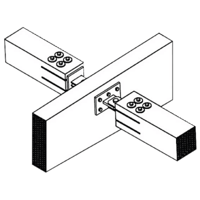
Pressure and tensile stiff connection
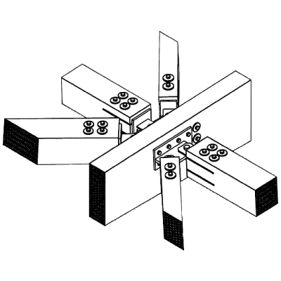
Association node
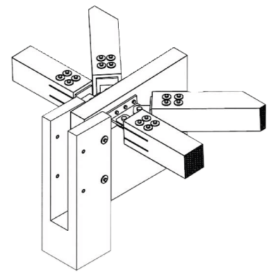
Connection beam support
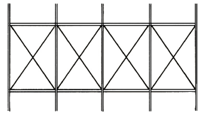
Crossed diagonals stressed only on tension
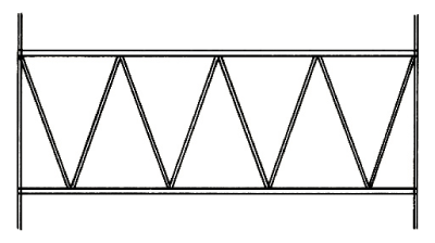
Rising and falling diagonals
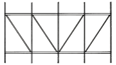
Falling diagonals
Technical
Data
| Span | 10 – 70 m |
|---|---|
| Roof pitch | – |
| Usual beam spacing (other dimensions possible) | 5 – 7 m |
| Beam width (2 cm preferred dimensions each) | 10 to 26 cm |
| Cantilevers | possible on both sides |
| Height of components (for structural design) | h1 = l/16 ; h2 = l/20 to l/25 |
| Possible fire resistance classes | R 30 > without problems R 60 > with additional costs |
| Preferred strength classes | GL 24h/c, GL 28c, GL 30c |
Glulam
Components parts
DERIX
Find your contact person
DERIX
Premium
Exklusive services, newsletter & Co.
Register now and get exclusive access to extensive specialist content. Use our helpful digital service tools such as our X-LAM Designer and stay well informed with our newsletter.